Chapter 4
Chapter 4 Slides(pptx)
Errata
Last updated 2019-10-08
- p.54 Note added to explain that the magnitude of complex field is not necessarily equal to the real field amplitude.
- p.54 Include prefactor of 1/sqrt(2) in eqns (4.6) and (4.7) to be consistent with (4.4) and (4.5).
- p.58 Eqn (4.13) Left-hand side should be a function of alpha not theta.
Extras
Linear polarization in the circular basis
Linear polarization as superposition of left- and right-circular
We can describe the polarization of light (Chapter 4 in Optics f2f) in terms of a superposition (or statistical mixture) of left- and right-circularly polarized components (see p. 55 in Optics f2f). For example, linearly-polarized light consists of a superposition of equal amounts of left- and right-circular as in the Figure below. If you click on the interactive version you can watch the time evolution (use the slider to move forwards and backwards in time).
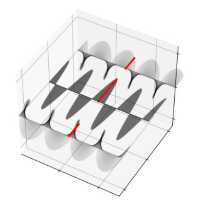
Click here to see interactive figure. The field propagates (forward in space and time) from left to right. Question: Is the left-circular component show at the front or back of the figure? Note how in space the left- and right-circular components for left- and right-handed screw. Note how in time (move slide from left to right to move forward in time), the E-field of the left- and right-circular components rotates anti-clockwise and clockwise respectively.
Or here for the python code that made this plot.
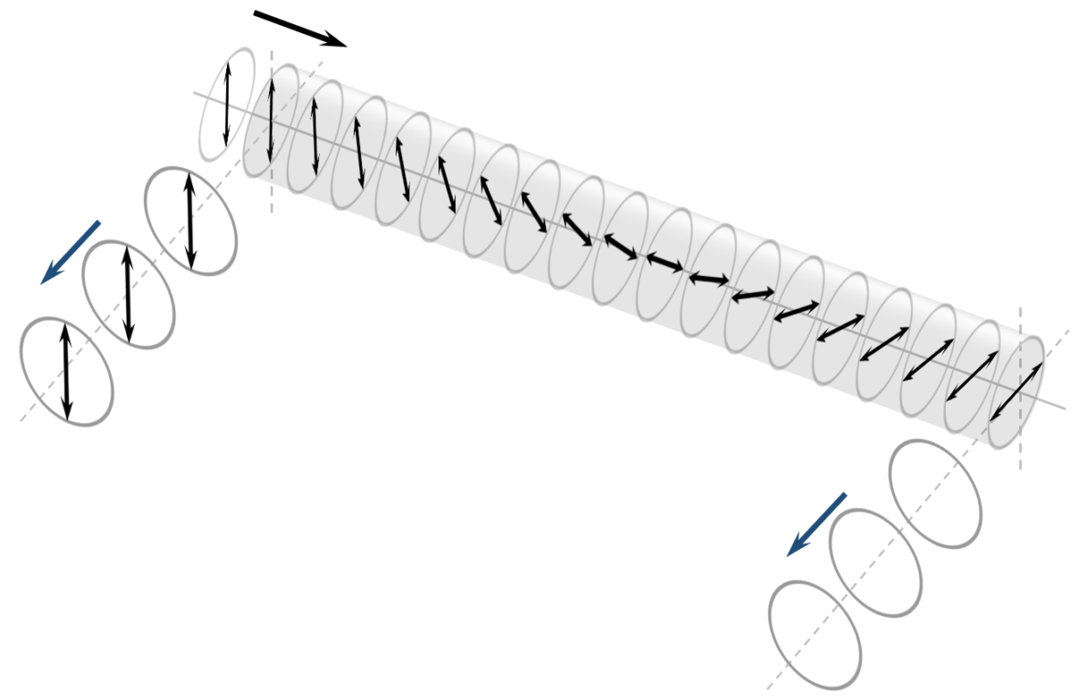
Rotation of the plane of polarization in a circularly birefringent medium
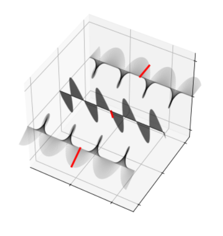
The field (shown in the centre) propagates from left to right and we have shown left and right components displaced towards the back and front, respectively. Notice, how as we move forward in time and look into the field, the left-hand and right-hand components (at a particular position as indicated by the red vectors) rotate anti-clockwise and clockwise, respectively.
An interesting effect occurs when we change the relative phase of the left and right components. Such a phase shift arises whenever light propagates through a circularly birefringent medium (p. 61 in Optics f2f), such as a solution of chiral molecules (e.g. sugar as discussed below) or an optical medium in a magnetic field. The effect of changing the relative phase (with time fixed) is illustrated in the next interactive figure.
Click here to see interactive figure.
Or here for the python code that made this plot.
We find the superposition remains linearly polarized but the plane of polarization rotates. This effect is the basis of optical activity and the Faraday effect (see p. 62 in Optics f2f).
Optical rotation in sugar
Of all experiments in optics, one can make a case that none pack more pedagogical punch then optical rotation in sugar. In one beautiful and simple experiment we learn about the physics of light scattering, polarization, chiral chemistry, and fluorescence.
History
Optical rotation was first discovered by Jean-Baptiste Biot in 1815, and has an almost immediate impact by providing a quantitative measure of the purity of sugar. [1] In 1848 Louis Pasteur establsihed chiral chemistry by using Biot’s optical rotation technique to distinguish between left- and right-handed tartrate crystals.
Experiment
The modern variant of the experiment is to send a laser beam through a sugar solution, for example, corn syrup which is liquid at room temperature and about 1/3 glucose by weight.
For the laser we use the Hexa-beam laser which has the advantages of 6 colours in one box. Below we show a photograph of the blue laser passing through a tube of corn syrup and viewing the scattered light from the side through polarizing sheets.
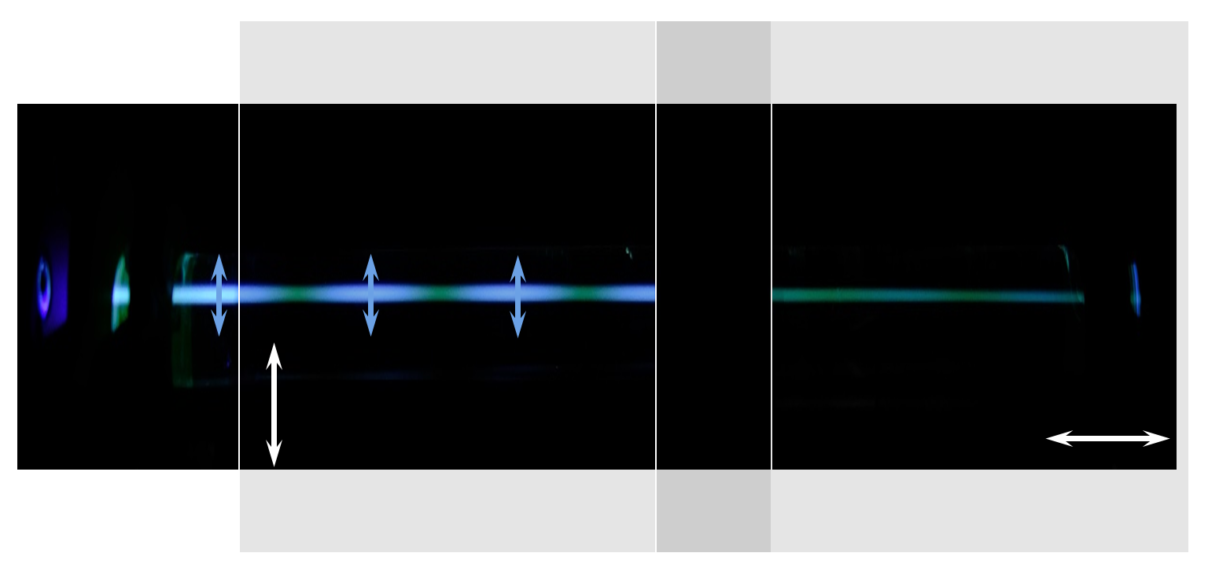
We can see the laser beam as it propagages through the sugar but oddly the green laser seems to oscillate between bright green and a fainter orange, whereas the blue laser oscillates between blue and green. What is going on?
Light scattering
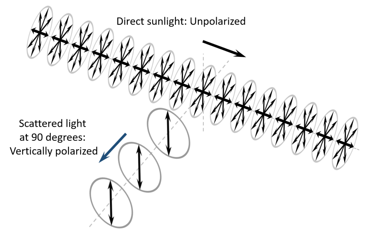
Given that we should never look directly at a laser beam we only ever see laser light because it is scattered. This light scattering effect is the same as we see in the sky. We are not looking at the sunlight directly, only sunlight that is scattered by molecules in the atmosphere (which scatter more blue than red, see p. 223 in Optics f2f).
If the light is propagating across our field of view and we are observing from the side then we only vertically polarized light is scattered. This is illustrated below for the case of unpolarized light propoaging from left to right and we observed vertically polarized light.
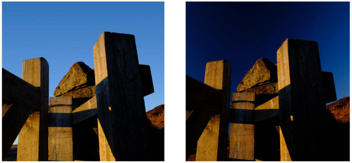
This effect is well known to landscape photographers who may exploit this effect using a polarizing filter. The images on the left and right below are taken with the polarizer aligned vertically and horizontally, respectively, allowing first vertical and second horizontally polarized light to pass. When we detect horizontal light (right image) the sky looks very dark because the scattered light is mostly vertically polarized and does not pass through the polarizer.
The difference in the sugar experiment is that the input is linearly polarized and we will only see scattered light from the side if the polarization is vertical and remains vertical. The fact that scattered green and blue in the experiment sometimes disappears suggests that the polarization might be changing as the light propagates.
Optical rotation
In fact, what happens is that the axis of linear polarization rotates, as shown in this figure.
The light starts out vertically polarized and we can see vertically polarized scattered light but then rotates to horizontal and we see nothing (in microscopic terms the electric charges in the sugar, cannot emit light in the direction of their oscillation, i.e. in the direction of the observer). As the light continues it rotates back to vertical and we see scattered light again. This explains the bands of light and dark observed in the experiment.
The reason for this rotation is that the sugar molecules are chiral (see p. 62 in Optics f2f).
As in landscape photography, we can verify the polarization of the scattered light by placing a linear polarizer between the object and the detector. Below we show what happens if we view the sugar experiment through both vertical (on the left) and horizontal (on the right) polarizing sheets. We have overlapped the two sheets slightly to show that through crossed polarizers we really do see nothing.
Through the vertical polarizers there is not much change, whereas through the horizontal polarizer all the scattered light (which is vertically polarized) is blocked and we see nothing. Well, not quite nothing. In fact we see some light of a different colour. This is fluorescence.
Fluorescence
In fluorescence, the incident light is absorbed (not scattered), both the polarization and the wavelength of the emitted light can be different to the input. In this example the fluorescence is unpolarized which is why we can see it through both the vertical and linear polarizers. By energy conversation the wavelength of the emission cannot be shorter than that of the input which explains why the green and blue lasers produce orange and green fluorescence, respectively.
[1] According to The Shadow of Enlightenment: Optical and Political Transparency in France 1789-1848 by Theresa Levitt, “the price of a batch of sugar was determined directly by its polarimeter reading”.